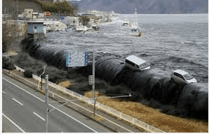
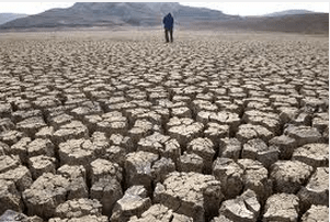
The climate is changing and the impact of such a change is felt almost in every sphere of life around the world especially in countries like India.
” Erratic monsoon rain patterns have left crops parched, jeopardizing India’s nearly $370 billion agricultural sector and hundreds of millions of jobs. Drought conditions are crippling vast swaths of India’s farmland as the country faces its driest monsoon since 2009. With more than 60 percent of India’s agriculture reliant on monsoon rains, farmers are highly vulnerable to changes in rainfall patterns and rising global temperatures, the Indian Council for Research on International Economic Relations found in a report” according to the International Business Times.
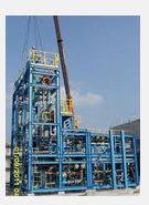
The situation in Australia is no different from India, both surrounded by ocean of water yet no water to irrigate or even to drink. Many scientific studies have clearly highlighted the close relationship between warming earth, increasing salinity of seawater and the climate change. But new coal-fired power plants and seawater desalination plants are set up almost every year in these countries. Both greenhouse gas and the increasing salinity of seawater will only contribute to intensify further warming of the earth. There is some awareness about the global warming by GHG (greenhouse gas emission)but there is no awareness about the increasing salinity of seawater. One of the largest desalination plant set up in the state of Victoria in Australia is idle for so many years yet unable to supply water to struggling farmers in the country Victoria. In a way it is a blessing in disguise because it would have otherwise discharged billions of cubic meters of RO concentrate with toxic chemicals into bass strait.
California law requires that any “new or expanded coastal … industrial installation using seawater” must utilize “the best available site, design, technology and mitigation measures feasible … to minimize the intake and mortality of all forms of marine life.” (California Water Code section 13142.5(b)
The following excerpts from NASA highlights the close relationship between
Ocean salinity and changing climate and rainfall.
“Salinity, Ocean Circulation & Climate
Surface winds drive currents in the upper ocean. Deep below the surface, however, ocean circulation is primarily driven by changes in seawater density, which is determined by salinity and temperature. In some regions such as the North Atlantic near Greenland, cooled high-salinity surface waters can become dense enough to sink to great depths. The ‘Global Conveyor Belt’ visualization (below) shows a simplified model of how this type of circulation would work as an interconnected system.
The ocean stores more heat in the uppermost three (3) meters than the entire atmosphere. Thus density-controlled circulation is key to transporting heat in the ocean and maintaining Earth’s climate. Excess heat associated with the increase in global temperature during the last century is being absorbed and moved by the ocean. In addition, studies suggest that seawater is becoming fresher in high latitudes and tropical areas dominated by rain, while in sub-tropical high evaporation regions, waters are getting saltier. Such changes in the water cycle could significantly impact not only ocean circulation but also the climate in which we live.
‘The Global Conveyer Belt’ (http://science1.nasa.gov/media/medialibrary/2013/05/20/thermohaline_assembled.) represents in a simple way how currents move beneath the wind-driven upper ocean. This movie begins by focusing on the North Atlantic east of Greenland, where cold surface waters get saltier due to evaporation and/or sea ice formation. In this region, surface waters can become dense enough to sink to the ocean depths. This pumping of surface water into the deep ocean forces the deep water to move horizontally until it can find areas where it can rise back to the surface. This very large, slow current — estimated to be on the order of 1000 years to complete a full circuit — is called the thermohaline circulation because it is caused by temperature (thermo) and salinity (haline) variations. Credit: NASA/GSFC
Launched June 10, 2011, aboard the Argentine spacecraft Aquarius/Satélite de Aplicaciones Científicas (SAC)-D, Aquarius is NASA’s first satellite instrument specifically built to study the salt content of ocean surface waters.
Salinity variations, one of the main drivers of ocean circulation, are closely connected with the cycling of freshwater around the planet and provide scientists with valuable information on how the changing global climate is altering global rainfall patterns.
The salinity sensor detects the microwave emissivity of the top 1 to 2 centimetres (about an inch) of ocean water – a physical property that varies depending on temperature and saltiness. The instrument collects data in 386 kilometre-wide (240-mile) swaths in an orbit designed to obtain a complete survey of global salinity of ice-free oceans every seven days.”
According to a new report on desalination in California
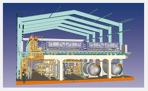
Desalination is the removal of salts from saline water (brackish or seawater) using distillation or membrane separation technologies in most cases. Current desalination technologies produce a toxic concentrated brine discharge that contains all the salts and dissolved solids along with process chemicals.
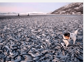
Putting the brine “cocktail” back into the ocean damages the marine environment and runs counter to the environmental goals of the state. The brine creates extensive damage in the ocean in areas sometimes called dead zones. The damage affects the environment, the economy, and the quality of life of the neighbouring areas on land and off shore.
Desalination is receiving increased attention as a means for addressing the water supply challenges of California. The state’s growing population, much of which is located in semi-arid regions, periodic droughts, and other water demands create pressure on existing water supplies and strong incentives to find new ones. (California Desalination Planning Handbook, Dept. of Water Resources, 2008, p.1) With the state’s 3,427 miles of Pacific coastline, (CA Water Plan, 2009, Volume 2, Strategic Resource Management, Chapter 26, Water‐Dependent Recreation. 26‐5) desalination of sea water is a reasonable response to the need for a reliable supply of more potable water—if it can be done without environmental damage.
New desalination technologies exist that produce no brine (and no concentrated brine cocktails). They should be chosen as best available technology (BAT) in the future.
The California report says:
“Consequences of all aspects combined
The brine cocktail damages many life forms – plant and animal; adults, larvae, and eggs. It kills some outright. It prevents reproduction for some. It impedes growth and thriving for some. And the damage can happen at only slightly elevated levels of concentration.
The hypoxic brine and chemical mixture is like plastic wrap suffocating the organisms living on the sea floor. Fish can swim away to better water conditions. Plants, eggs, larvae, and stationery or slow-moving animals like coral, clams, and crabs cannot.
In a comprehensive review of published studies about the impacts of desalination plant discharges, David A Roberts and team reviewed 8 field studies and 10 laboratory experiments that examined a range of salinities and a variety of organisms from waters in the US and Spain. They concluded that experiments in the field and laboratory clearly demonstrate the potential for acute and chronic toxicity, and small-scale alterations to community structure following exposures to environmentally realistic concentrations of desalination brines.
The observed effects of the tests in the study mentioned above included fertilization, germination, growth and development, and mortality on seven organisms. The study was focused on the effects of several brine concentrations and used brine prepared in the laboratory or taken from an RO plant discharge.
It did not look at the effects of the chemical additives or exposure over long terms. Even so, it found effects over limited time periods on several species at some state of development and varying concentrations. For many marine invertebrates the larvae are especially susceptible to brine concentrations.”


Both energy and water are increasing in demand as the population grows and it is critical to choose the right type of technology to sustain such a growth. Wrong choices made due to popularity or quick fixes will lead to long-term consequences. Desalination with zero liquid discharge should be a mandatory so that large multinational companies will at least spend some funds on R&D towards achieving such a goal. Otherwise it will continue to be a “business as usual”.